Installation and commissioning
Instructions for installation and commissioning.
Name, article number and e-number
Name | Article number | E-number (SV) |
|---|---|---|
PoE Switch 8p PS OUT S | PL02P00048P050P-UTS | 51 73 418 |
PoE
[sv] Om
[sv] PoE Switch 8p PS UT S är en strömförsörjning med PoE för utomhusbruk. Byggd för att klara nordiska förhållande - sommar som vinter. Produkten skiljer sig från inomhus-batteribackuper från Milleteknik och vissa funktioner har tillkommit och andra har fallit från.
Revisions and the edition of this document
The current and most recently published edition of this document is available at www.milleteknik.com.
The validity of this document can not be guaranteed, as new editions are published without prior notice.
Instructions for use in Swedish in original.[1].
Instructions for use, technical data and translations thereof may contain errors. It is always the responsibility of the installer to install the product in a safe manner.
Symbols
Symbols | Denomination | Explanation |
|---|---|---|
 | Warning | Risk of electric shock, improper installation or hot surfaces. Appears in some manuals |
 | Note | Used for supplementary information that clarifies the text. |
 | Caution/Important | Indicates the risk of equipment damage or malfunction. Also used for information that is important but not security-related |
 | Tips | Displays practical advice or shortcuts for installation, operation, or service. |
 | CE marking | The product complies with applicable EU directives and harmonised standards. |
 | Read the manual | Please read manual before installation and service. |
 | Do not dispose of in household waste | The product is covered by the WEEE Directive and must not be disposed of with household waste, it must be recycled and delivered to a recycling centre. |
 | Recycling | Packaging, products and other materials that do not contain electronics must be recycled in accordance with local environmental regulations. |
Installation — general information
Installation shall be carried out by a competent electrician in accordance with the applicable national electrical installation rules.
The product is of protection class I and must be connected to a grounded 230 V AC circuit.
A main switch according to IEC 60947-1 shall be provided in the fixed installation. The switch should be easily accessible and clearly marked with its function.
The area of the supply cable shall be at least 1,0 mm² and fitted with a fuse T 2,5 A (slow-blown) or equivalent.
AC and low voltage cables must not be pulled together. Keep separate cable chutes or bundles
Check that protective earth (PE) is properly connected before turning on voltage.
Ensure free air circulation around the enclosure at least 100 mm, unless otherwise specified. Ventilation openings must not be covered.
The product is intended for indoor installation in normal environment (pollution number 2 and indoor class 1).
These general requirements apply to all Milleteknik products with 230 V mains connection.
Requirements for main switch, fuse and cable area
In order to comply with applicable electrical safety requirements, the installation shall be equipped with a main switch according to IEC 60947-1.
Component | Requirements |
|---|---|
Main switch | A main switch according to IEC 60947-1 shall be included in the installation and be easily accessible. Separated phase (F) and neutral (N) |
Fuse | The supply circuit shall be protected by a fuse or automatic fuse with rated current according to the product specification (normally T 2,5 A slow-blown or equivalent). Refer to the device's nameplate. |
Fuses | Approved type according to IEC 60127. |
Cross-sectional area (230 V) | At least 1,0 mm2 |
Cable length | In the case of longer wiring, voltage drops should be taken into account so that the operating voltage does not fall below 230 V ± 10% at the unit. |
Strain relief | All cables must be properly secured and strain relief checked before energizing the unit. |
These requirements apply to all Milleteknik products with 230 V mains connection.
The table below shows recommended cable area for low current installations at different voltages, current strengths and cable lengths. Values are based on copper cable and a maximum voltage drop of approximately 3% to ensure operational reliability.
Enclosures
[sv] Montering utomhus
[sv] Produkten är avsedd för montering på stolpe med skenor eller motsvarande fästdetaljer.
[sv] Använd skenor och infästningar som är kompatibla med produktens vikt och monteringsmönster.
[sv] Montera skenorna i produkten innan stolpfästen eller rörklämmor monteras.
[sv] Placera rörklämmor eller motsvarande fästdetaljer runt stolpen och anslut dem till skenornas monteringspunkter.
[sv] Kontrollera att produkten är riktad och monterad i vertikalt läge innan åtdragning.
[sv] Stolpens diameter och material ska vara lämpligt för vald typ av fästdetalj.
[sv] Dra åt samtliga skruvar och muttrar enligt fästdetaljens rekommendationer.
[sv] Säkerställ att produkten sitter fast och inte kan rotera eller glida på stolpen efter montering.
[sv] Kabelinföringar ska orienteras nedåt eller enligt produktens specifika installationsanvisningar.
[sv] Undvik placering där vatten kan rinna direkt ned på kapslingen från ovanliggande ytor.
[sv] Montering ska utföras enligt gällande installationsregler och av behörig installatör.
[sv] Montering på stolpe
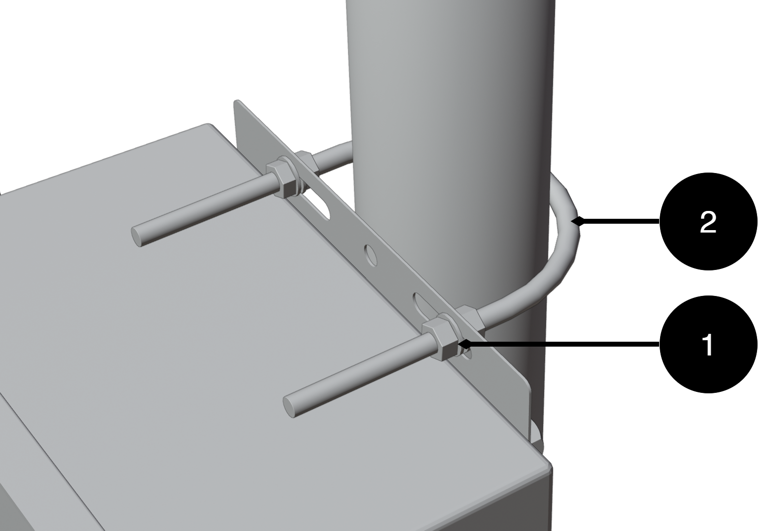
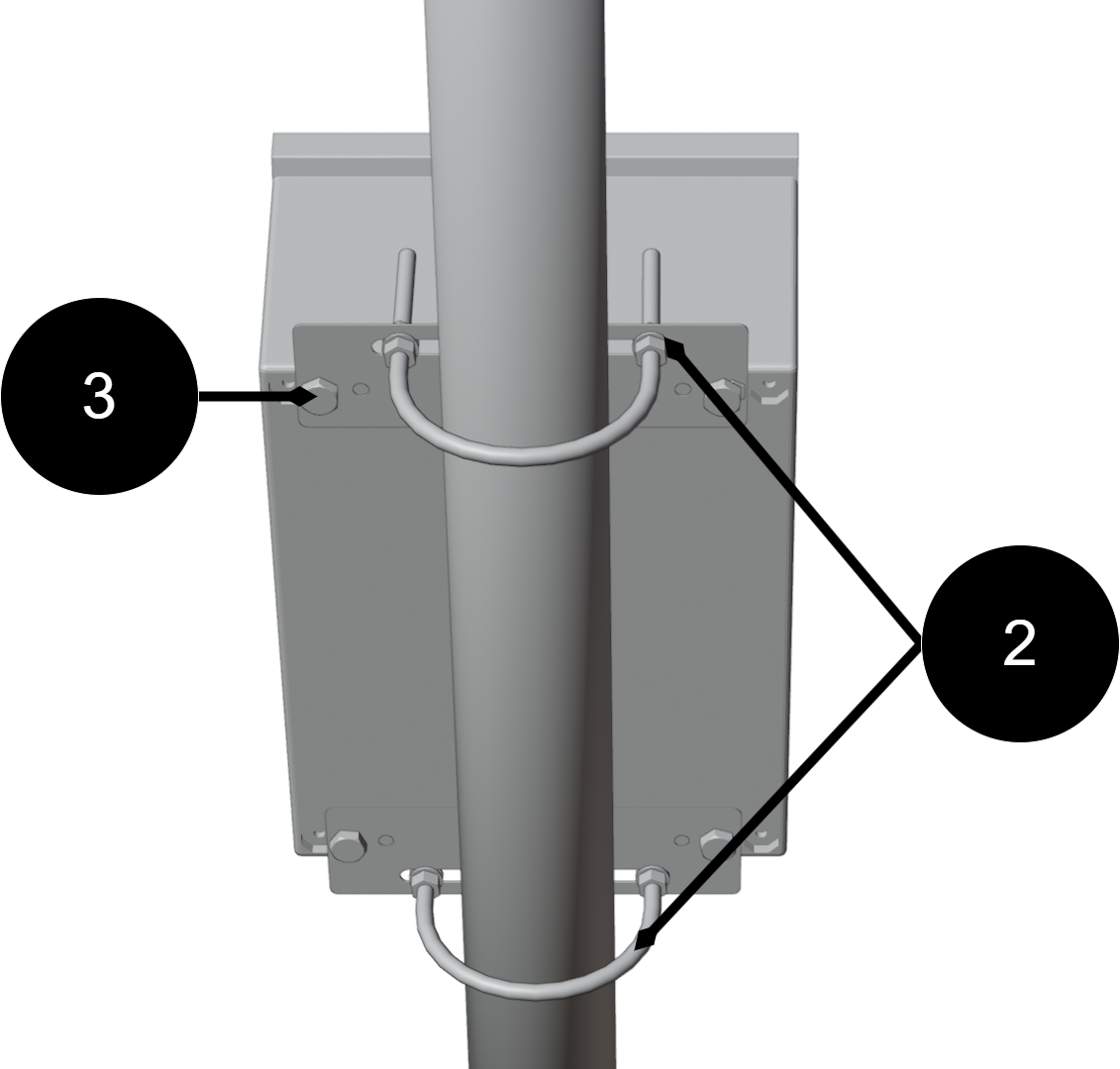
[sv] Montering på stolpe
[sv] Montera i denna ordningen:
[sv] Placera fästplåtarna (3) på kapslingens övre och nedre infästningspunkter och fäst dem lätt med medföljande skruvar. Dra inte åt slutligen ännu.
[sv] För den nedre U-bulten (2) runt stolpen och genom hålen i den nedre fästplåten. Montera brickor och muttrar. Dra åt lätt.
[sv] För den övre U-bulten (2) runt stolpen och genom hålen i den övre fästplåten. Montera brickor och muttrar.
[sv] Justera kapslingens läge så att den är i lod och centrerad mot stolpen.
[sv] Dra åt alla muttrar i turordningen: – nedre U-bult – övre U-bult – skruvarna till fästplåtarna
[sv] Kontrollera infästningen genom att belasta kapslingen lätt framåt/bakåt för att säkerställa stabil montering.
Component overviews
[sv] Komponentöversikt monteringskit
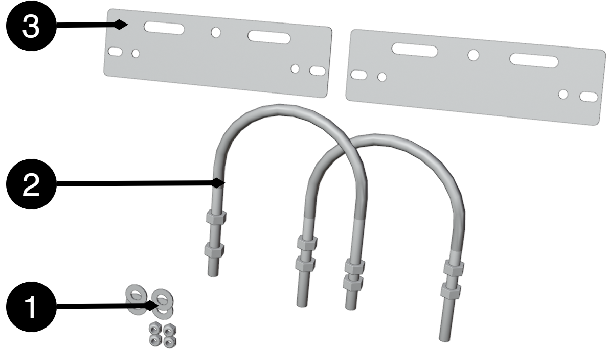
[sv] Nr | [sv] Förklaring |
|---|---|
1 | [sv] Fästplåt |
2 | [sv] U-bult för stolpe |
3 | [sv] Brickor och muttrar |
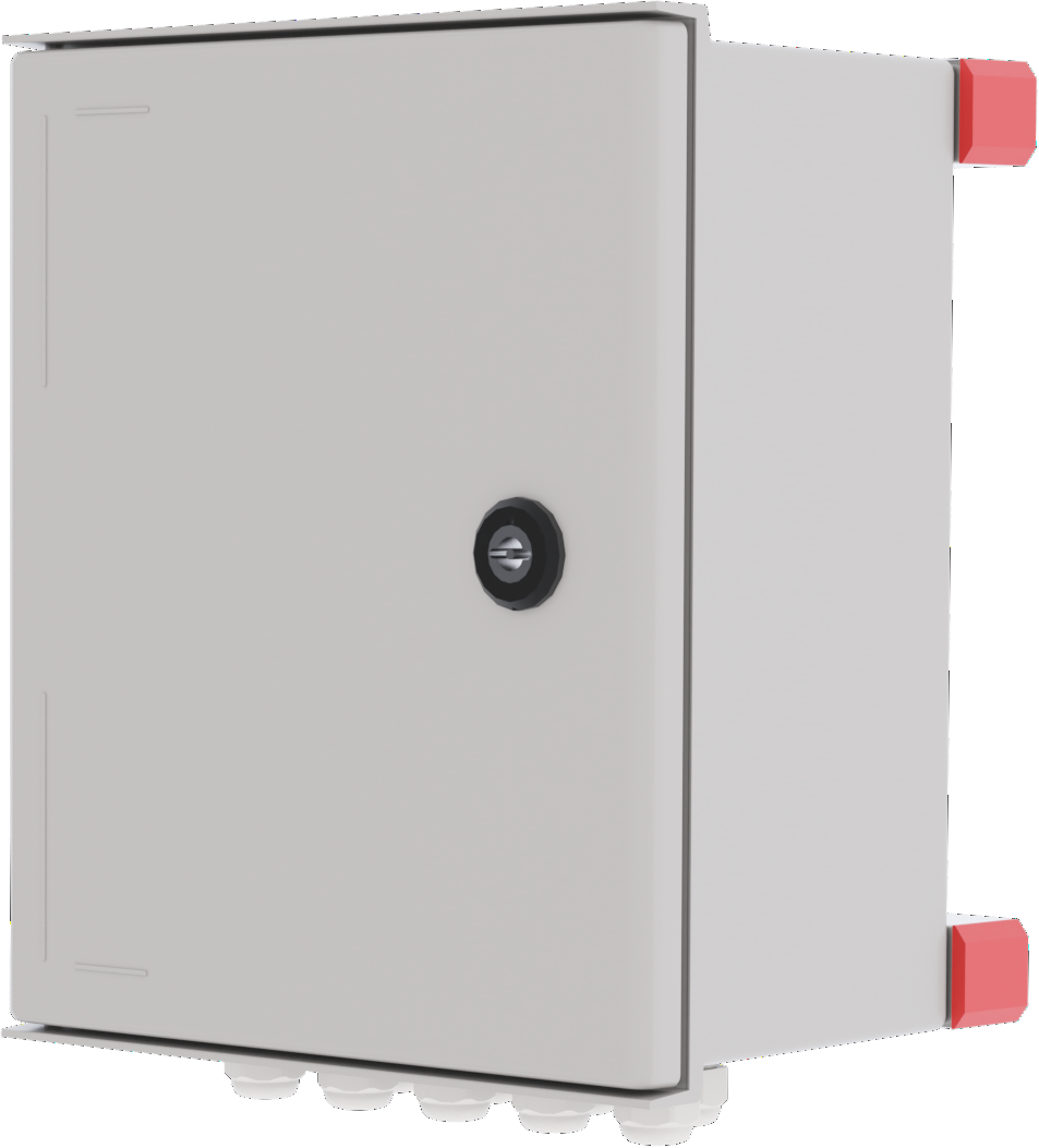
Component overviewNOVA FLX L

[sv] Bokstav | [sv] Förklaring |
|---|---|
A | [sv] Kabelgenomföringar. |
B | [sv] Dörr. |
C | [sv] Lås. |
D | [sv] Inkoppling- /åskskyddskort. |
E | [sv] PoE-kort. |
F | [sv] Nätaggregat. |
G | [sv] Fäste på baksida. |
H | [sv] Fästskruv. |
[sv] Kortbeskrivning 230 V inkoppling, 24 V DC ut och åskskydd
![[sv] Kortet är tredelat och kan delas upp för att erhålla önskad funktion.](image/uuid-e2fb4779-efe7-ab4e-8c1d-93079cc3d00b.png)
[sv] Kortet har tre delar, det är inte säkert att alla konfigurationer har alla delar av kortet.
[sv] Beteckning | [sv] Förklaring | |
|---|---|---|
[sv] 1A | [sv] Inkoppling 230 V AC inkommande. | |
[sv] A1 | [sv] Fas (F) | |
[sv] A2 | [sv] Neutral (N) | |
[sv] A3 | [sv] Jord (PE) | |
[sv] 1B | [sv] Inkoppling till nätaggregat. | |
[sv] 1C | [sv] Nätsäkring. | |
[sv] Beteckning | [sv] Förklaring | |
|---|---|---|
[sv] 2D | [sv] 24 V DC strömmatning från nätaggregat. | |
[sv] 2E | [sv] Larm | |
[sv] E1 | [sv] NC | |
[sv] E2 | [sv] COM | |
[sv] E3 | [sv] NO | |
[sv] 2F | [sv] 24 V ut. | |
[sv] F1 | - | |
[sv] F2 | + | |
[sv] Beteckning | [sv] Förklaring | |
|---|---|---|
[sv] 3G | [sv] 24 V DC in | |
[sv] G1 | - | |
[sv] G2 | + | |
[sv] G3 | [sv] PE | |
[sv] 3H | [sv] Extern jordanslutning (i kapsling/jord). | |
[sv] 3I | [sv] Larm | |
[sv] I1 | [sv] NO | |
[sv] I2 | [sv] COM | |
[sv] I3 | [sv] NC | |
[sv] 3J | [sv] Potentiometer, ställbar +/- | |
[sv] 3K | [sv] LED, lyser gult vid jordfel. | |
[sv] Inkoppling av strömmatning
[sv] 230 V kopplas in på plint 1A.
[sv] Teknisk beskrivning (ML - fyll i här)
[sv] Vad gör kortet?
[sv] Tekniska specifickationer:
[sv] Anslut matningsspänning, 230 V AC
[sv] Matningsspänning kopplas in på plinten.
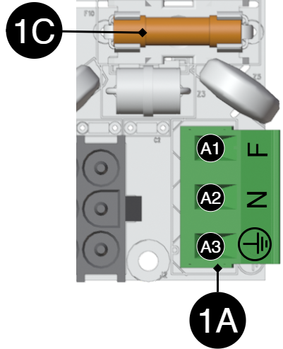
[sv] Beteckning | [sv] Förklaring | |
|---|---|---|
[sv] 1A | [sv] Inkoppling 230 V AC inkommande. | |
[sv] A1 | [sv] Fas (F) | |
[sv] A2 | [sv] Neutral (N) | |
[sv] A3 | [sv] Jord (PE) | |
[sv] 1C | [sv] Nätsäkring. | |
[sv] Driftsättning - hur enheten skall startas
Danger
Personal injury or death can occur if the device is connected to the mains or live when disassembling / moving.
[sv] Anslut last.
[sv] Anslut nätspänning.
[sv] Koppla in nätspänning.
Maintenance
The system with the exception of batteries is maintenance-free when installed in an indoor environment.
Product sheet - power supply / battery backup
Product sheet - power supply from Milleteknik
PoE
Name, article number and e-number
Name | Article number | E-number (SV) |
|---|---|---|
PoE Switch 8p PS OUT S | PL02P00048P050P-UTS | 51 73 418 |
Area of use
Power supply to power PoE devices such as surveillance cameras and other PoE powered devices.
Long life, energy efficient and support is available if something goes wrong, now or in 10 years.
Common uses
Supports IP cameras, readers, door centers and other networked security devices
Power and data distribution over a single network cable for simplified installation.
Used to power IP-based access systems where both data and power go through network cabinets.
Technical description
PoE switch with eight PoE fed ports and two LAN ports and one sfp port. Power supplies power PoE cards. The device lacks batteries, so backup power in case of power failure is not possible
Voltage, current and power
Mains voltage: 230 V AC - 240 V AC, 47 Hz - 63 Hz.
Power: 240W and 30.8W per port. 48V power supply directly from power supply.
Load outputs
PoE switch can drive load to PoE devices and external power supply can drive one (1) 24 V load output to power other applications.
Protection
Protection against: Overvoltage, overtemperature and short circuit.
Indications and communication
Communication via software in switch. Indications on LEDs on switch
Enclosure
Box in fiberglass reinforced acrylic plastic.
Weight
Name | Net weight | Weight incl. packaging |
|---|---|---|
PoE Switch 8p PS OUT S | - | - |
Installation requirements
The device is intended for fixed installation. Ambient temperature: – 15°C to +35°C.
Requirements that the product meets
EMC: | EMC Directive 2014 / 30EU |
Electricity: | Low voltage directive: 2014/35 / EU |
CE: | EC Directive in force: 765/2008 |
Emissions: | |
Immunity: | EN61000-6-2:2005, EN61000-4-2, -3, 4, -5, -6, -11 SS-EN 50 130-4:2011 Edition 2, EN50131-6 |
Machinery Directive | The product is part of electrical systems, is subject to the relevant electrical and safety directives and is not a machine according to the Machinery Directive (2006/42/EC). |
Ecodesign | Milleteknik's products are intended for professional use and are therefore not directly covered by the Ecodesign Regulation (EU 2019/1782). As some components may be covered, we nevertheless disclose relevant information to give our customers confidence in their choice |

Guarantee
Expandable, options and accessories
The product cannot be expanded.
Manufacturing, lifespan, environmental impact and recycling
Manufactured by Milleteknik in Partille, Sweden.
Link to technical specifications
Links to manuals and product sheets
You can find manuals and product sheets at: www.milleteknik.se The QR code below takes you to the product page.
Name | Dimensions | Batteries that fit | Link |
|---|
Batteries are only included if specified, otherwise batteries will need to be purchased separately.
Miscellaneous
The difference between PoE, PoE+ and PoE++.
About this information
All information is published subject to possible errors. Information is updated without prior notice. [sv] [sv] |
Publication date 2025-12-12
Address and contact details
Milleteknik AB |
Ögärdesvägen 8 B |
S-433 30 Partille |
Sweden |
+46 31 340 02 30 |
info@milleteknik.se |
www.milleteknik.com |
[1] Translations in languages other than Swedish are indicative only and not safely reviewed. Translation should always be checked against the Swedish original to ensure accurate information